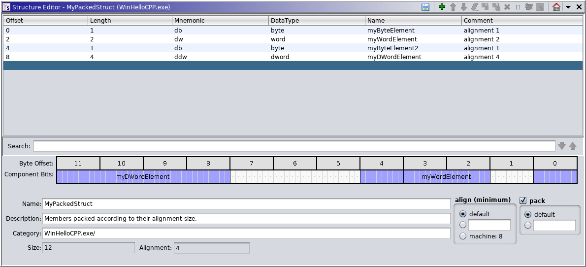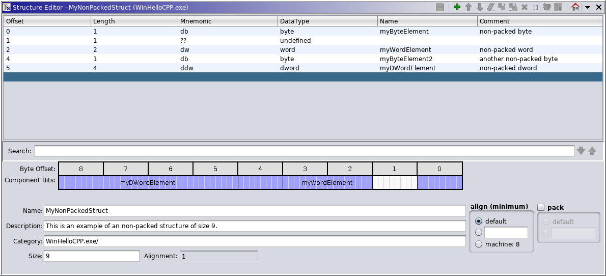
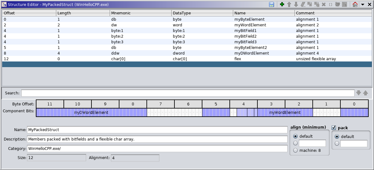
The Structure Editor is used to define the contents of a structure data type. It can be used to create a new structure or to modify existing ones. Structures are user defined data types that contain components. A component is a data type of a particular size and at a specified offset in the structure. The following illustrates the editor for a structure data type.
As shown above, the Structure Editor also includes a bit-level view of the structure layout to improve
understanding of bitfield placement when they are present. Note that the byte ordering is
reversed for little-endian data organizations to ensure that a bitfield is always rendered
as a contiguous bit range. If inadequate space is available for a component label,
within the bit view of the component, it will be omitted. However, holding down the Shift-key
while using the mouse wheel on a component will zoom the view in and out
allowing component labels to appear when space permits. The bit view may also be used to make
and reflect single component selections with the table. Within the bit view any padding bits not visible within
the table view as a component will include a small dot in the center of the displayed bit cell.
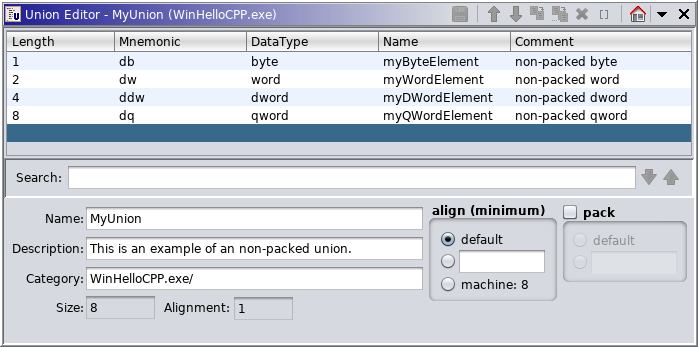
The Union Editor is very similar to the Structure Editor, but is used to create or modify a union data type. All the components of a Union are at an offset of 0. The following illustrates the editor for a union data type.
A Structure Editor or Union Editor can be launched from the Data Type Manager, the Code Browser, or the Structure or Union Data Type Editors.
The Structure and Union Editors are composed of the following:
- Edit Actions: The icon buttons at the top of the editor are used to modify this structure. Each button has a different edit action associated with it. These allow the user to: apply changes, insert Undefined components, reorganize the current components, duplicate components, clear components (changes them to undefined components), delete components, create array components, and unpackage a structure or array component changing it into its component parts.
- Pull Down Menu: The
icon at the top of the editor provides additional editor actions. These are: show the category path of a component's data type, edit a component's data type, edit the fields of a component, apply a cycle group or favorite.
- Component Table: The upper portion of the editor contains a table with the structure's or union's components. Each component (or row) consists of its offset, length, mnemonic, data type, field name, and comment. See the Component Fields section for more about these fields. The data type, field name and comment are editable fields. The data type's category can be determined by showing the data type category. Components can be added, inserted or replaced in the table using Drag and Drop or by applying a Favorite data type. The data type for a component can also be changed by cycling the data type.
- Structure Information Area: This is the area below the component table with the name, description, category, size, packing and alignment of the structure or union. The structure or union being edited can be renamed from here. Its description can be specified here.
- Immediately below the structure information area is a status line where status messages will appear.
Select the Apply Changes icon
in the toolbar to apply the changes from the editor back to the program or archive.
If editor changes to a structure or union are applied and it is assigned to data in the program, all data items with the structure or union as the data type now have the new data type. In other words, the size or composition of those data items in the program will have changed due to the apply.
Select the
icon in the toolbar to have the editor's data type be highlighted in the Data Type Manager's tree.
Select the Close dockable component icon
in the toolbar to exit from the editor. If you have unsaved changes to your data type, a dialog will ask if you want to save the changes.
To search for text in any column on any row in the editor, enter the text into the Search field and press return to search forward from the currently selected table row. Alternatively, the down
and up
arrows next to the search field can be used to search forwards and backwards respectively. Searches are not case sensitive.
The default name of each structure field will also be examined when searching, even though they are not visible in the UI.
To change the name of the structure or union being edited, edit the Name field in the bottom of the editor. If the name is valid, the structure's or union's name will change when the edits are applied by pressing the editor's Apply Changes icon
To change the description of the structure or union being edited, edit the Description field in the bottom of the editor. The structure's or union's description will take effect when the edits are applied by pressing the editor's Apply Changes icon
To change the size of the structure being edited, edit the Size field in the bottom of the editor and press the Enter key to apply the new size to the structure. If you are reducing the size of the structure, you will be prompted to determine that you really want to truncate the structure. The ability to specify the size is only permitted for non-packed structures. For other situations the field is read-only.
At the bottom of the editor is a read-only Alignment field which conveys the actual alignment of this data type. All non-packed structures and unions (i.e., pack disabled) will have a default alignment of 1 (byte aligned) unless a minimum alignment value has been specified. For packed structures and unions the actual alignment value is calculated based on the pack setting, preferred alignments of the individual components, and the minimum alignment setting. The size of a packed structure or union will always be a multiple of this alignment value. This value is always expressed in terms of 8-bit bytes.
This alignment is considered when this data type, or derivative data type, is placed within another packed composite. A compiler will also utilize this when placing components within memory although Ghidra does not enforce such placement.
In the lower right corner of the editor is a series of pack choice buttons. The disabled button corresponds to a non-packed structure or union, while the default or value-entry buttons enable packing.
Non-Packed Structures
When packing is disabled for a structure all bytes are accounted for by the displayed components. Use of undefined filler components as padding and reservation of space. This differs from a packed structure which does not reveal padding in the form of components and does not provide a means of reserving space. Non-packed structures may be used to position components with known data types at specific offsets within a structure whose size has been specified. When editing a non-packed structure the editor attempts to prevent defined components from moving to a different offset when performing operations like drag and drop which may consume undefined bytes. The default alignment for non-packed structures is 1-byte but may be overriden by setting a specific non-default minimum alignment. The alignment will not influence the size of a non-packed structure so it is advised that the size always be explicity set to a multiple of the alignment value.
Packed Structures
A packed structure is defined similar to a structure in a C header file and is intended to automatically adjust component placement, size and alignment in a manner consistent with the associated compiler specification. Data types are specified for each of the components, but their offsets are automatically computed based upon the pack settings and preferred alignment of each component's data type. A default datatype (i.e., undefined) cannot be added to a packed structure, although other sized datatypes (e.g., undefined1, undefined4, etc.) may be used as component place-holders and will pack appropriately based upon their size. The overall size of the structure is determined by the components it contains, the pack setting (default or explicit value) and the minimum alignment setting. The default alignment and pack behavior is controlled by the effective data organization. This can cause the same structure viewed within a program to be layed-out quite differently than within a datatype archive which uses a default data organization.
The following image shows the editor state reflecting a default packed structure with default alignment.
align (minimum)
This setting controls the minimum alignment to be used when computing this data type's actual alignment.
- default - Sets this data type to compute its default alignment based only on the pack setting and the alignment of the individual components. If packing is disabled (i.e., explicit component placement by offset) the default alignment will always be 1-byte and preferred component alignments are ignored.
- explicit value - The radio-button with a text field next to it allows you to specify an explicit minimum alignment value. This sets the data types minimum alignment. The computed alignment for the data type will be a multiple of this value.
- machine - Sets the minimum alignment to conform to the machine alignment specified by the associated data organization (i.e., compiler specification). This genrally corresponds to the largest alignment which is ever used for any data type on the program's intended machine. If this is choosen and the resulting alignment is larger, this is likely due to a component data type having an alignment larger than the machine alignment.
pack
This setting controls the packing behavior of the structure or union. In general, packing should be disabled when a complete definition is unknown and it is neccessary to reverse engineer the component specifications. This is the initial state of a new structure with the pack checkbox left unchecked. When a the specifications of a composite are known, such as from a source header file, it may be preferred to enable packing to allow for automatic placement of components and calculation of alignment and size. To enable packing the pack checkbox should be checked and either a default or explicit pack value specified.
- default - The components within this structure should align besed upon the preferred alignment of each component.
- explicit value - The button with a text entry field next to it allows you to specify an explicit pack value. The specified value indicates the maximum alignment to use when packing each component.
When packing is enabled, the padding at the end of a structure will be adjusted to ensure an overall size which is a multiple of the computed alignment. If an explicit pack value is specified the, the aligned placement of components will not exceed this value. In addition, the computed alignment will not exceed this value if a default is selected for the align (minimum) setting. If a minimum alignment other than default is specified, the computed alignment and overall size will be a multiple of the align value regardless of the pack setting. The align setting will not influence interior component placement as does the pack setting.
Non-packed Unions
When a union is not packed (i.e., pack disabled), the union is the size of its largest component. There is no alignment padding and the default alignment is 1. As with structures, a minimum alignment may be specified to force a specific alignment. The alignment will not influence the size of a non-packed union so it is advised that the size always be explicity set to a multiple of the alignment value.
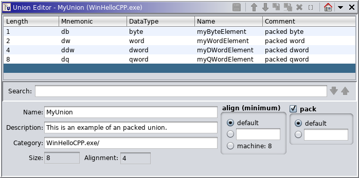
Packed Unions
In a packed union the overall size is at least the size of the largest component, but will be padded based on the actual computed alignment. The minimum alignment is specified in the same manner as for a structure and affects the alignment in the same way. The pack value is specified in the same manner as within a structure, but only affects the trailing padding and overall size of the union. All elements in a union have an offset of zero, so the pack value doesn't affect the component offsets. If both a minimum alignment and pack value are specified, the minimum alignment will override the pack value if it is larger.
A structure and union may define bitfield components which attempt to model bitfield definitions found within C/C++. Unlike other byte-oriented components, bitfield components have the following characteristics:
- A bitfield datatype may not exist anywhere other than within a structure or union.
- A bitfield datatype may not be selected via the datatype chooser or tree since it requires the specification of additional attributes (e.g., bit-size, bit-offset). The bit-size is generally appended to the base datatype for datatype specification and presentation purposes (e.g., char:1).
- A zero-length bitfield may be defined within a byte but its precise bit position is controlled by endianness alone. A zero-length bitfield has no affect within a non-packed structure and is intended for use within packed structures where it may impart alignment affects based upon compiler conventions.
- Inserting a bitfield within a non-packed structure may cause component shifts based upon the specified offset and allocation unit byte size when a placement conflict occurs.
- The start/end byte offsets may be shared with adjacent bitfield components.
- Unoccupied bits within a partially occupied byte are not represented by any component (similar to padding bytes within packed structures).
- A separate Bitfield Editor, for use with non-packed structures only, must be used to precisely place a bitfield component. Adding a bitfield component via the structure table view via datatype text entry (e.g., char:1) provides only rough placement for non-packed structures since additional bytes will be introduced. The BitField Editor may be displayed using the the Add Bitfield and Edit Bitfield popup menu actions on a selected structure component. The datatype text entry approach must be used for all unions and packed structures.
While packing of bitfields within packed
structures is controlled by the compiler specification (e.g., data organization), bit-packing
order is currently fixed based upon endianness. Little-endian packs starting with bit-0 (lsb)
while big-endian packs starting with bit-7 (msb).
The use of bitfield components is not
currently reflected in decompiler results or assembly markup.
A structure may be defined with zero-element array components, also referred to as a flexible array, which correspond to an unsized array (e.g., char[0]). Such a component is created by simply specifying a zero-element array datatype as you would a sized-array component (see Create Zero-Element / Flexible Array Component). The resulting component will not consume any space within the structure and will report a component size of 0. As such, it may reside at the same offset as a subsequent component and/or may have an offset equal to the length of the structure. When packing is enabled such a component may influence the overall alignment of the structure and its length.
The use of flexible array components is not
currently reflected in decompiler results or listing reference markup. Its primary purpose
if to reflect the C/C++ source definition of a structure with correct alignment and structure sizing.
The edit actions are available both from the icon buttons in the editor and from the popup menu for the component table. To display the popup menu, right mouse click on the component table. There are also short-cut keys associated with each of the edit actions.
Insert Undefined Byte
Within a non-packed structure undefined components are inserted before the current selection by clicking the
Move Up
A contiguous group of components can be moved up or down in the structure. Select a block of one or more components. Each time the
Move Down
Select a block of one or more components. Press the
Duplicate Component
To duplicate a component within a structure or union:
- Select the component.
- Press the
- A single copy of the component is created immediately following the selected one. The newly created component will become selected allowing for repeated use of the action.
If the structure is not packed (i.e., pack disabled), then there must be enough undefined components following the component to accommodate the duplicate. In such a such a structure, undefined bytes get consumed by the new copy of the component. If action is performed on the last component the structure length will grow as needed.
Duplicate Multiple of Component...
To create multiple copies of a component:
- Select the component.
- Press the
- The number of duplicates dialog appears. In a non-packed structure, you can only indicate as many duplicates as will fit in place of undefined bytes unless duplicating the last component in which case the structure will grow as needed. The last component added will become the selected component.
- Enter a valid number of duplicates and press the Enter key or the OK button.
- The specified number of copies of the component are created immediately after the selected one.
Delete Component(s)
One or more components can be deleted from a structure or union. Deleting components in a structure will cause the components that come after those being deleted to shift to new offsets.
To delete components:
- Select one or more components to delete.
- Press the
- The components are removed from the structure or union.
Clear Component(s)
Clearing a component changes it into an undefined components that take up the same amount of space as the component being cleared. Components can only be cleared in non-packed structures (i.e., pack disabled), but not in unions or packed structures. This is because the resulting undefined components are not valid in a union or packed structure.
To clear components in a structure:
- Select one or more components in the table.
- Press the
- Each selected component is replaced by undefined components. The number of undefined components will be equal to the length of the component being cleared.
Create Array
To create an array from a single selected component:
- Specify the number of elements. For a non-packed structure (i.e., pack disabled), the maximum size of the array is limited by the number of undefined components following the selected component.
- Press the OK button.
- The selected component becomes an array of that same data type with the specified dimensions.
To create an array from a selection of multiple components in a structure:
- Select multiple contiguous components.
- Press the
- An array is created. The data type of the first component in the selection is used as the data type of the array. The array's dimension is determined by how many of that data type will fit in the space that was occupied by the selection. The size of the array will be the array that can fit in the selected number of bytes. Any left over (unused) bytes at the end of the selection will become undefined components.
To create an unsized flexible array component you must use the datatype cell edit feature to select/enter the datatype by name including the array-sizing-specification (e.g., char[0]). To initiate edit mode for a component datatype you must double-click the datatype cell for the component you wish to modify. This may be an existing component or the empty row at the end of the table. See Editing the DataType Field for more details.
Unpackage Component
Unpackaging takes a single component and replaces it with its own component parts. When editing a structure, array and structure components can be unpackaged by selecting that component and clicking the
Create Structure From Selection
Creating a structure from a selection takes a contiguous selection of components in the structure editor and creates a new structure from those components. It then replaces the selection with a single component whose data type is the new structure. The components that were in the selection will become the components that make up the new structure. The user does this by selecting the components in the editor and clicking the
It is important to note that when using this action with a packed structure the placement of components within the new stucture may change as can offsets of trailing components within the current structure. The size of the current structure may also be affected as a result of this change.
If you do not like the result of the change you can restore the previous state of the current structure by using the action on the new structure component, although the newly created structure will still exist within the Data Type Manager.
The following bitfield actions are available when modifying non-packed structures only (i.e., pack disabled) and are available via the popup menu based upon a selected component or table row. When working with unions and packed structures, bitfields may only be specified via datatype text entry specification within the table view (e.g., char:1).
Add Bitfield
With a structure row selected in the vicinity of the desire bitfield placement, the popup menu action (right mouse-click) Add Bitfield may be selected to launch the Bitfield Editor for a new bitfield.
Edit Bitfield
With a defined bitfield component row selected, the popup menu action (right mouse-click) Edit Bitfield may be selected to launch the Bitfield Editor.
Each row displays information about a component in this structure or union. The DataType, Name, and Comment fields are editable.
The following summarizes the information about each field for a component.
Offset - The byte offset of this component from the beginning of the structure. For unions the byte offset of all components is zero, and therefore this field isn't shown.
Length - The length of this component in bytes.
Mnemonic - The mnemonic (brief identifier) for this component's data type.
DataType - The data type of this component. This field is editable.
Name - The field name associated with this component in the structure or union. When specified, the field names must be unique for the components in a structure or union. This field is editable, except on undefined components.
Comment - A comment associated with this component. This field is editable, except on undefined components.
To rearrange the order of the component
fields position the cursor over the header for the table column. Left mouse click and drag the
column left or right to its new position.
Editing Component Fields
The DataType, Name and Comment fields are editable. However, the Name and Comment are not editable on undefined components.
To place an editable field into edit mode:
- Double click on an editable field.
or
- Select a single component row and press F2 to begin edit mode. This puts the first editable field in that component row into edit mode. Tab will then move to the next editable field.
Applying an Edit
In the editable field, pressing Enter applies the value to the field if it is valid and ends the edit session. If the field's value is invalid, a message is written to the editor's status line and the field remains in edit mode.
Canceling an Edit
In the editable field, pressing Escape cancels the edit session without applying the changes to that field.
Editing More Than One Component Field
You can move directly from editing the component 's name or comment field to editing another by pressing Tab, Shift-Tab, UpArrow or DownArrow. The key press only moves the edit session if the current field edit can be applied. Otherwise, an error is displayed in the status line.
Tab
Pressing Tab applies the current edit and moves to the next editable field in the table. If the current field is the last editable one in this component then it moves to the first editable field in the next component. This key moves the edit session left to right and top to bottom in the table.
Shift-Tab
Pressing Shift-Tab applies the current edit and moves to the previous editable field in the table. If the current field is the first editable one in this component then it moves to the last editable field in the previous component. This key moves the edit session right to left and bottom to top in the table.
Up-Arrow
Pressing the UpArrow key applies the current edit and moves to the same field of the previous component in the table if that field is editable. This key moves the edit session bottom to top in the table.
Down-Arrow
Pressing the DownArrow key applies the current edit and moves to the same field of the next component in the table if that field is editable. This key moves the edit session top to bottom in the table.
Editing the DataType Field
To edit the data type double-click the data type cell. This will show the Data Type Selection Dialog, which allows you to easily enter a data type or select/modify an existing one from one of the open datatype managers. It can also be Undefined, a pointer to a datatype, or an array.
- Fit (non-packed structure only) - when modifying a component there must be adequate space to place the component. Any undefined components which immediately follow the modified component may be consumed or added based upon the component size change. It may be neccessary to insert undefined bytes or clear other components before the modification may be completed.
- Illegal Datatype - certain datatypes are not permitted (e.g., data driven Dynamic types, Factory types).
- Zero-Length Components (non-packed structure only) - modification of an existing zero-length component may not change its size.
Examples of datatypes which may be specified, include:
This can be any fixed-length built-in data type (e.g., byte, word, etc.), structure, union, typedef, or enum.
Sizable Dynamic Data Type
A sizable built-in Dynamic data type such as string may be specified in which case the user will be prompted to specify the component size.
Pointer Data Type
This can be a named Pointer data type (e.g., pointer, pointer16, etc.) or a pointer to a specific data type. A pointer to a data type is indicated by following the data type name with an * (i.e., asterisk symbol). It is also possible to stipulate a specific pointer-size, although it should be only done when the default pointer size is inappropriate. A stipulated pointer size may be specified by following the * with its bit-size (16,24,32..64). The pointer * designation may also be stacked for a pointer-to-pointer type.
For example, word* is a pointer to a Word using the default pointer size. If a non-default size is needed word*16 would force the use of a 16-bit pointer.
Array
A single or multidimensional array of any basic data type may be specified.
For example, dword[2][4] is an array with 2 elements, where each element is an array with 4 elements that are DWords; In a similar fashion a zero-element character array may be specified as char[0].
Array of Pointers
Arrays of pointers may also be specified.
For example, float*[5] is an array with five elements where each element is a pointer to a Float.
Bitfields
A bitfield may be specified by appending :<bitsize> to the end of a valid base datatype. Valid base datatypes include all integer types (e.g., byte, char, int, etc.), a defined enum, or a typedef which corresponds to an integer-type or enum. It is important to note that specifying a bitfield in this manner works well for packed structures, however for non-packed structures it may be neccessary to use the Bitfield Actions to properly define a bitfield.
For example, int:4 defines a signed integer bitfield which is 4-bits in length.
Effect of Changing a Component's Size
A non-packed union's size will always be the size of its largest component. If you change a data type for a component and the component size changes, the union size will change if necessary. A packed union is padded to make its size a multiple of the union's alignment.
How a structure is affected by changing a component's data type depends on whether the structure size is packed or non-packed.
Non-Packed - If the structure has pack disabled, then the new component must be less than or equal to the original component's size plus any undefined components that immediately follow it in the structure. Decreasing the component size will create undefined components following it to maintain the structure size and placement of other components. Increasing the component size replaces undefined components immediately following the component. The last component of a structure can always be changed which can cause the structure to grow larger.
Packed - If the structure is packed, a component can change size or alignment, which can affect the placement of subsequent components within a structure and/or the overall size and alignment of both structures and unions.
Editing the Name Field
When specified, a field name must be unique for the components in a structure or union. It cannot contain blanks.
Editing the Comment Field
The comment can be any Ascii text.
Pressing the 'p' key invokes the pointer action on a component. This will generally create a default pointer unless the existing data is already a pointer in which case that pointer will be wrapped with an additional pointer (e.g., int * would become int **). This action will always apply a default sized pointer. Otherwise you can drag one of the other pointer types from the Data Type Manager window. With existing pointer data, the base type of that pointer may be changed simply by applying another type onto the pointer (e.g., applying byte to default pointer becomes db *). If you do not want this pointer stacking behavior to happen, it is best to clear the code unit(s) before applying a data type via drag-n-drop or key-binding actions.
Some data types are part of a cycle group. A cycle group is a collection of data types that are similar and are commonly associated with one another. Cycling a data type facilitates changing a component from one data type to the next data type in the same group. Each cycle group has a short-cut key associated with the group. Pressing the short-cut key cycles from the current data type to the next one in the group. For example, the b key is associated with the Byte cycle group. This group is Byte, Word, DWord, and QWord.
Union or Packed Structure
The first data type in a cycle group can be added to the end of a structure as a new component.
To add a data type using a cycle group key:
- Select the last row (the blank row) of the component table.
- Press the short-cut key for the desired cycle group. For example, the b key will add a Byte; the f key will add a Float; the apostrophe key will add an Ascii.
To cycle a component's data type to another one in the same group:
- Select the component in the table.
- Press the cycle group key until the data type has cycled to the desired data type. For example, if the current data type is a Byte, pressing the b key twice would change it to DWord.
Non-Packed Structure
Cycling is implemented similar to how it is implemented in a packed structure. The only exception is that the user can only cycle to data types that will fit within the data boundary of the current component. If undefined components follow the selected component, the component can be replaced by cycling the data type to a larger sized data type. Likewise, cycling to a smaller data type will add undefined components after the component being cycled. However, the last component is not restricted to a particular size.
Data types can be dragged from the Data Type Manager to the component table in the Structure Editor. A regular drag and drop results in the component in the editor being replaced by the one being dragged. Holding the Ctrl key during the drag and drop causes the dragged data type to be inserted instead of being replaced.
Known Problem: Holding the Ctrl key to perform an insert of a data type does not currently work on a Mac. On a Mac try using the Alt key to insert rather than the Ctrl key. The "+" should then appear at the drop site.
Favorite data types are defined from the Data Type Manager dialog. In the Data Editor, favorites are available through the popup menu in the component table. Applying a favorite data type is similar to dropping a data type. Favorites can be used to insert a component of that data type or to replace a component's data type. Favorites can only be applied to a contiguous selection. Therefore, individual favorites are only enabled when they can be applied (i.e. they fit at the selection and the selection is contiguous).
Favorites are discussed further in Adding a Data Type, and Replacing a Data Type.
A data type can be added as a component by replacing undefined components. When editing a non-packed structure, there must be enough undefined components for the new data type. A data type can also be added to the end of a structure or union.
Drag and Drop
Drag a data type from the data type manager to the empty row at the end of the component table and drop it. The data type is added to the end of the structure in the editor.
If the data type can be various sizes, the user is prompted for the desired size. The following illustrates the dialog due to the drag and drop of a string.
Simply enter the number of bytes desired for the data type and press the Enter key or click the OK button.
Favorites
Right mouse click on the empty row at the end of the table and pull right to see the Favorites. Select the favorite from the popup and it is added as the last component.
In a packed structure or a union, a data type can be inserted as a new component.
Drag and Drop
- While holding down the Ctrl key, drag the data type you want to insert from the data type manager. As you drag it over the components in the structure editor, the drag icon will have a "+" on it indicating insert mode.
- Release the mouse button when you are on the desired component and the dragged data type is inserted before it.
Known Problem: Holding the Ctrl key to perform an insert of a data type does not currently work on a Mac. On a Mac try using the Alt key to insert rather than the Ctrl key. The "+" should then appear at the drop site.
A component can have its data type replaced with a different data type. If a non-packed structure is being edited then undefined components are created or consumed as necessary to maintain the position of other components within the structure. For unions and packed structures, the data type simply changes for the component and the overall size is adjusted accordingly.
Drag and Drop
Single Component Selected
Drag a data type to a single selected component in the editor or to a non-selected component in the editor. If the mouse pointer is a 'circle with a slash' then the data type cannot be dropped to replace the component. This is probably because the data type being dropped won't fit in the structure in place of the original component. If editing a union or packed structure the data type will always fit and the drop is allowed (provided the datatype is allowed). If editing a non-packed structure, the component is replaced only if the new component will fit. (see Effect of Changing a Component's Size)
Contiguous Selection of Multiple Components
Drag a data type to a block of selected components. Whether the structure is packed or non-packed doesn't matter when dropping a data type on a block of selected components. This is because the new component (s) will occupy the same space as the currently selected components.
In a union, all selected components will be replaced with a single component containing the data type dropped.
In a structure, as many components of the dropped data type as will fit in the selection are created to replace the selection. In a non-packed structure any left over bytes in the selection will become undefined components.
Favorites
Single Component Selected
To replace a component's data type with a favorite data type, select it in the table, right mouse click and pick the favorite. Only favorites that will fit in place of the component will be enabled. (see Effect of Changing a Component's Size)
Contiguous Selection of Multiple Components
To replace a contiguous selection with a favorite data type, select it in the table, right mouse click and pick the favorite.
In a union, all selected components will be replaced with a single component containing the favorite data type.
In a structure, only favorites that will fit in place of the selection will be enabled. Just like with drag and drop, whether the structure is packed or non-packed doesn't matter. The selection becomes as many of the data type as will fit and left over bytes become undefined components for a non-packed structure.
Every component has a data type: Byte, Word, Float, etc.. The category is where that data type is located. Since you can have two data types with the same name in different locations (categories), the editor provides a way to see the category for any component's data type.
To see the category for a component:
- Select a single component.
- Right mouse click on the component in the table.
- From the popup menu, select Show Component Path.
- The category information appears in the editor's status line at the bottom of the dialog.
Another Data Type Editor can be brought up from within the Structure Data Type Editor for any component that is an editable data type, such as Structure, Union, or Enum. In addition, another Data Type Editor can be brought up for any component whose base data type is an editable data type. For example, a Typedef on a Structure would allow you to edit the Structure. Likewise, you can edit a Structure wherever the component is a Pointer to the Structure.
To display another editor for a component that has an editable data type:
- Select the component with a data type that is a structure, union or enum or that has one of them as its base data type.
- Right mouse click on the component in the table. Select Edit Component... from the popup.
- The editable data type for the selected component is displayed in a new data type editor.
The Component Table contains numeric fields such as the component's offset and length. The structure information area also shows the overall size and alignment of the structure. By default, numbers are initially shown as hex values in the Structure Editor. There is a tool option, Show Numbers In Hex, that lets you override the default and set whether these numbers should be displayed as decimal or hex values when an editor is initially displayed.
The hex/decimal mode can quickly be toggled using the key binding Shift H or the toolbar menu item in the editor. Changing this only affects the current editor where it is changed.
To switch between decimal and hex display of numeric values in the current editor, press Shift H or use the menu action as follows:
- Right mouse click on the table.
- A check mark next to Show Numbers in Hexadecimal indicates that numbers are currently displayed in hex. If there is no checkmark, the numbers are currently shown in decimal.
- From the popup menu, select Show Numbers in Hexadecimal.
- The numbers being displayed will change from decimal to hexadecimal or vice versa. The check mark next to Show Numbers in Hexadecimal indicates whether the numbers are currently displayed in hexadecimal.
The Structure and Union Editors add options to the tool. To view or edit the option settings:
- From the tool's menu select Edit
Tool Options... which displays the Tool Options Dialog.
- Open the Editors tree node.
- Click on either the Structure Editor or Union Editor tree node to view its options.
The StructureEditor and Union Editor tabs contains the following options:
Editor Option Functionality
Structure Editor Show Numbers In Hex If selected, the component offsets and lengths as well as the overall size and alignment of the structure will be displayed in hexadecimal when a new Structure Editor is initially displayed.
Otherwise, the lengths are initially in decimal.
Union Editor
Show Numbers In Hex If selected, the component lengths as well as the overall size and alignment of the union will be displayed in hexadecimal when a new Union Editor is initially displayed.
Otherwise, the lengths are initially in decimal.To select an option simply click on the check box.
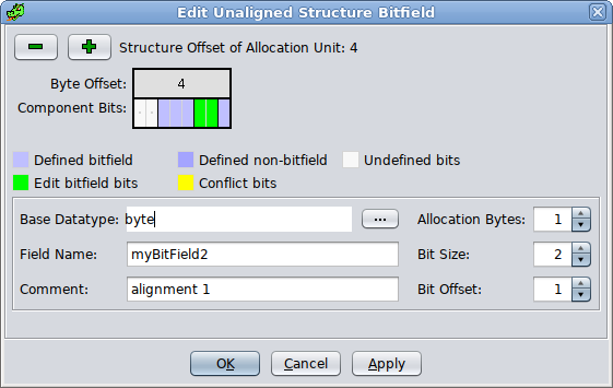
The Bitfield Editor is used by the Structure Editor when adding or modifying bitfield components within non-packed structures to facilitate precise placement at the bit level. The Bitfield Editor is not supported for unions and packed structures since automated packing is performed (i.e., bitfields are specified via datatype text entry within the structure/union table view). While editing a non-packed structure, the Structure Editor popup menu actions Add Bitfield and Edit Bitfield are used to launch the Bitfield Editor.
The Bitfield Editor includes a visual depiction of the storage allocation bytes and associated bits (8-bits per byte, with a left-to-right / msb-to-lsb sequence of 7..0 ). The displayed byte ordering as conveyed by the Byte Offset header will differ for big-endian vs. little-endian. This is done to ensure that bitfields which span byte boundaries will always visually appear as a consecutive range of bits. The Component Bits display provides both a popup menu and mouse assisted bitfield manipulations. Component labels are included within each component when space permits. The color legend indicates the bit color scheme reflecting Defined bitfields, Defined non-bitfields, Edit bitfield bits, Conflict bits and Undefined bits. A dot in the center of an Undefined bit indicates a padding bit not included within any defined component. Conflict bits correspond to the current edited bitfield where bits have been specified in conflict with an existing component.
While the Bitfield Editor is displayed local popup menu actions are provided which can facilitate additional component manipulations (e.g., Add Bitfield, Edit Bitfield, Delete). These actions relate to the component at the current mouse cursor location. An addition popup menu toggle action available over the bitfield viewer is Show Byte Offsets in Hexadecimal. Invoking either the Add Bitfield or Edit Bitfield local popup menu actions will immediately cancel the current bitfield operation if one is active.
Bitfield Parameters
Structure Offset of Allocation Unit - controls the minimum byte offset of the storage allocation unit represented by the bitfield edit view. This offset is controlled via the
and
Allocation Bytes - controls the size of the storage allocation unit to be utilized in the event a bit conflict exists and the user chooses to Move Conflicts. This numeric entry can be directly entered within the range of 1 through 16 bytes. The mouse wheel may also be used while the cursor is over this entry.
Bit Size - specifies the size of the bitfield in bits. This size may not exceed the size of the specified Base Datatype. This numeric entry can be directly entered or via the mouse wheel while the cursor is over this entry field or the rendered bitfield.
Bit Offset - specifies the offset of the rightmost bit of the bitfield within the displayed allocation unit. This numeric entry can be directly entered or via the mouse wheel while the cursor is over this entry field.
Base Datatype - (required) specifies the numeric datatype associated with the bitfield. Valid datatypes include primitive integer types (e.g., char, bool, int, etc.), enum types, and typedef types of integer or enum types. This input allows direct text input with auto-complete assistance or via full access to a datatype tree chooser by clicking the '...' button.
Field Name - (optional) specifies the structure component name to be assigned to the bitfield. This entry utilizes a simple text entry field.
Comment - (optional) specifies the structure component comment to be assigned to the bitfield. This entry utilizes a simple text entry field.
Provided by: Data Type Manager Plugin