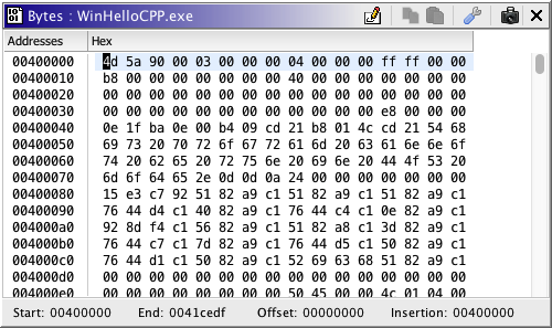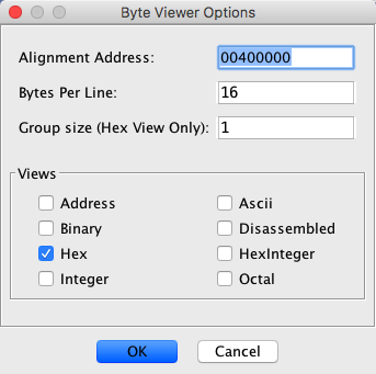
The Byte Viewer displays bytes in memory in various formats, e.g., Hex, Ascii, Octal, etc. The figure below shows the Byte Viewer plugin in a separate window from the default tool, the Code Browser.

To show the Byte Viewer, select the icon,  ,
on the Code Browser toolbar, OR, choose the Window
 Bytes: ... menu.
The following paragraphs describe the Byte Viewer.
This section describes the formats that Ghidra provides by default. Each format is an instance of a DataFormatModel interface, so any new formats that you provide will automatically show up in the Byte Viewer Options dialog that lists the data formats that may be added to your view. To add or remove a data format view from the tool, press the
icon to bring up the Byte Viewer Options dialog. Select the formats that you want and press the OK button.
Hex
The Hex view shows each byte as a two character hex value. Change the group size for the Hex format to show the bytes grouped in that size. When you add the Byte Viewer plugin to a tool and then open a program, the Hex view is automatically displayed by default.
This view supports byte editing.
Ascii
The Ascii view shows each byte as its equivalent Ascii character. For those bytes that do not represent an Ascii character, the format shows it as a tic (".").
This view supports byte editing.
Address
The Address view displays a tic (".") for all bytes whose formed address does not fall within the range of memory for the program. For those addresses that can be formed and are in memory, the view shows the symbol,
So if you go to that address in the Code Browser, and make a Pointer data type, the address pointed to is in memory. Conversely, if you go to a "tic" address in the Code Browser and make a pointer, the address pointed to is not in memory (the operand is rendered in red).
This view does not support editing.
Disassembled
The Disassemble view shows a "box" (
) symbol for each address that has undefined bytes. For those addresses that are instructions or defined data, the view shows a tic ("."). With this view, you can easily see what areas of the program have been disassembled.
This view does not support editing.
Hex Short
This format shows two-byte numbers represented as an four-digit hex number.
This view supports editing. When a byte is changed, both bytes associated with this address are rendered in red to denote the change.
Hex Integer
This format shows four-byte numbers represented as an eight-digit hex number.
This view supports editing. When a byte is changed, all four bytes associated with this address are rendered in red to denote the change.
Hex Long
This format shows eight-byte numbers represented as an 16-digit hex number.
This view supports editing. When a byte is changed, all eight bytes associated with this address are rendered in red to denote the change.
Hex Long Long
This format shows 16-byte numbers represented as an 32-digit hex number.
This view supports editing. When a byte is changed, all 16 bytes associated with this address are rendered in red to denote the change.
Integer
This view shows four-byte numbers represented in decimal format.
This view does not support editing.
Octal
The octal view shows each byte as a three character octal value.
This view supports editing.
Binary
The binary view shows each byte as an eight character binary value.
This view supports editing.
The labels below the scroll pane that contains the views shows the following information:
Start The minimum address of Memory End The maximum address of Memory Offset Displayed in decimal, the number of bytes added to each block of memory that is being displayed. This number is calculated when you set the alignment address or the number of bytes per line. Insertion The address of your current cursor location
To enable byte editing,
- Toggle the Enable/Disable Edit toolbar button
so that it appears pushed-in.
- Click in a view that supports editing, e.g., Hex or Ascii
- The cursor changes to red to indicate that this view can be edited.
Changing bytes is allowed only if your cursor is at an address that does not contain an instruction. If you attempt to change a byte of an instruction, an "editing not allowed" message is displayed in the status area of the tool.
Changed bytes are rendered in red. This color can be changed via the Byte Viewer Edit Options by double-clicking on the Edit Color field.
Undo the edit by hitting the Undo button (
) on the tool. The byte reverts to its original value. Redo your edit by hitting the Redo button (
).
To turn off byte editing, click the Enable/Disable Edit toolbar button
so that it no longer appears pushed-in.
If you have two Byte Viewers running, you can connect the two tools for the "Byte Block Edit" event so that when you make changes in one Byte Viewer, the other will reflect those changes in red.
The format view that currently has focus shows its cursor in magenta. (Cursor colors can be changed via the Options dialog) If the byte editing is enabled and the view that is in focus supports editing, then the cursor is red.
The Byte
Viewer Options dialog can be used to add and remove views, set the
Alignment Address, set the
number of bytes per line,
and set the group size to be
used by the hex view.
To launch the Byte Viewer Options dialog,
press the  icon on the Byte Viewer toolbar.

Alignment Address
The alignment address specifies what address should appear in column 0. Any address can be specified, but the address will be normalized to be near the program's minimum address. This enables you to view bytes in an offcut manner and to identify patterns in the bytes. Changing the alignment address affects the offset, which is the column that would display the bytes for address 0 if it existed. The offset is affected by both the alignment address and the bytes per line. The offset is displayed as a label below the scroll pane containing the views.
Sometimes you might see a byte pattern such that you want all the bytes to line up in the first column of the display. Consider the cursor position in the image below. If you want to see the fourth column of bytes (values of 00) to appear in the first column, you would enter an alignment address of 0040b003, as indicated by your cursor position.
The result of setting the alignment address to 0040b003 is shown below. The calculated offset is 13, the number of bytes added to each memory block to create a new alignment. The first line of the display shows the "remainder" bytes of 16 (bytes per line) divided by 13, the offset. If you were to put your cursor on the starting byte of the first line, you would see that your insertion point is 0040b000, in this example.
Set Bytes Per Line
The bytes per line indicates how many bytes are displayed in one line in a view. The default value is 16.
All formats shown must be able to support the new value. For example, since the HexInteger and Integer formats show bytes in groups of four, the bytes per line must be a multiple of four. If a selected format cannot support a value for the bytes per line, an error message will appear and the OK button will be disabled.
Set Group Size
The group size is the number of bytes that the Hex view shows as a "unit." For example, a group size of two means to show two bytes grouped together with no spaces.
View Selection
Each potential view is listed as a checkbox. Select the checkboxes corresponding to the views to be shown. Red text indicates a view cannot be displayed since it doesn't support the specified number of bytes per line.
The various views in the ByteViewer can be reordered by dragging the view header to the left or right of its current position. The view positions are swapped.
The width of each view can also be changed by dragging the separator bars in the view header to the left or right. This will resize the view that is to the left of the separator bar.
To supply your own format to be added to the list of views displayed in the Byte Viewer,
- Write an implementation of the ghidra.app.plugin.core.format.DataFormatModel interface, which determines the format of how the bytes should be represented.
- Edit your Plugin path to include your class files if you are running Ghidra in production mode versus development mode; in development mode, you will have to add your class files to your classpath in your development environment.
- Restart Ghidra.
Provided by: Byte Viewer Plugin